Y mx b In this formula m is a line of the slope and b is intercept of y in the line. The line is defined by two Endpoints.

Engineering Design And Cad A B Line Types Flashcards Practice Test Quizlet
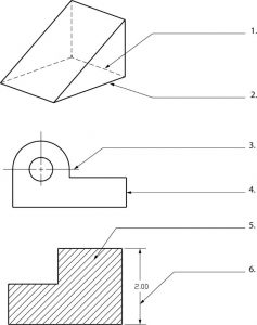
The representation of the object in figure 2 is called an isometric drawing.
. Look the most like photographs of all pictorial drawings. M _ W _ _ 1015 - 1130 Credits. When you want to make the letters of a line of text narrower you would set its.
Its density should be separate from the length of the line. A A hidden line has precedence over a center line. A quiz completes the activity.
A line is a part of a straight line that extends in the opposite direction indefinitely. Engineering Drawing Plays a crucial role in the life of Every Mechanical Engineering student because he has to bear that subject throughout his BTech. Fall 2013 MECH 211 Mechanical Engineering Drawing WELCOME TO.
An engineering drawing is a type of technical drawing that is used to convey information about an object. Word language Describe size location and specification of the object. The technical drawing is a form of design communication based on line symbols recognized and understood worldwide.
Any of the line objects - line arrow curved arrow polyline or freehand -- can be used to generate an XY dataset. The length of the second drawing is 10 mm. MCQ quiz on Engineering Drawing multiple choice questions and answers on Engineering Drawing MCQ questions quiz on Engineering Drawing objectives questions with answer test pdf for interview preparations freshers jobs and competitive exams.
Multiview drawing Axonometric drawing. Engineering Drawing course and in minimizing discrepancies. Copying Line Objects and Pasting Data to a Worksheet.
Put simply these lines are for drawing the objects. Select the line object in the graph then right-click and choose Copy. If isometric projection of an object is drawn with true lengths the shape would be same and size is how much larger than actual isometric projection.
To 2nd drawing RF. Of the midpoint of a line and the Y coord. In the case of isometric projection three-dimensional objects are represented visually in two dimensions in technical and engineering drawing.
Of the center of a circle and draws it 12 long in the positive X direction. Bhuiyan Shameem Mahmood Graphics language Describe a shape mainly. Elements of Engineering Drawing Engineering drawing are made up of graphics language and word language.
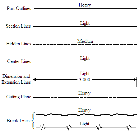
A drawing is a graphic representation of an object or a part of it and is the result of creative thought by an engineer or. The length of the long dashes varies according to the size of the drawing and is approximately 20 to 40 mm. Apart from the Engineering Drawing Production Drawing and Machine Drawing was also need.
This set of Engineering Drawing Multiple Choice Questions Answers MCQs focuses on Isometric Drawings. Here you can download materials of Engineering drawing Pdf Notes - ED Pdf Notes with latest and old materials with different links. In this highly interactive object learners associate basic line types and terms with engineering drawing geometry.
Basic Knowledge for Drafting Graphics language Word language Lec. The most common is a continuous line also known as a drawing line. In positions x1.
Find the 1st drawing length. After obtaining the X coord it prompted need YZ that means it has an X value and is looking for the rest you can build a new point by extracting each coord. 105 Pictorial Drawing Perspective Drawings A perspective drawing Is a three-dimensional representation of an object as it looks to the eye from a particular point.
The above starts a line at 2x1 from the X coord. An angle formed by two radial line from the center of the circle. Hence technical drawing is often referred to as.
Lines on the receding planes that. The ratio of 1st drawings RF. An isometric view of an object can be obtained by choosing the viewing direction such that the angles between the projections of the x y and z axes are all the same or 120.
Two dimensions of an object is shown. This is one of a family of three-dimensional views called pictorial drawings. Rotate Tilt More than one view is needed to represent the object.
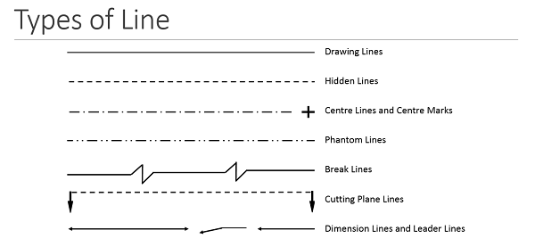
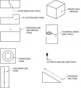
Line B-B is composed of alternating long and two short dashes which is one of the two standard methods. Three dimensions of an object is shown. For a very large section view drawing the long dashes are made very long to save drawing time.
Technical drawings provide clear and accurate information how an object is to be manufactured. Applying the dimensioning components Extension line dimension line and dimension number Mostly done by using Leader line and note The appropriate method depends on the objects features. A common use is to specify the geometry necessary for the construction of a component and is called a detail drawingUsually a number of drawings are necessary to completely specify even a simple component.
Orthographic view depends on relative position of the object to the line of sight. Basic Types of Lines Used in Engineering Drawings By Kelly Curran Glenn Sokolowski. With respect to the actual object is found to be 2.
Artistic Drawings range in scope from the simplest line drawing to the most famous paintings. Not every line on an engineering drawing is equal. C A visible line has precedence over a miter line.
It shows and describes clearly and accurately the information required to build or manufacture a product. 27 10 45 o Notes Detail of a local note depends on the objects features. In an isometric drawing the objects vertical lines are drawn vertically and the horizontal lines in the width and depth planes are shown at 30 degrees to the horizontal.
Lecture 1 Introduction Time. B A center line has precedence over a visible line. The formula for a line interception of the slope.
Professionals Teachers Students and Kids Trivia Quizzes to test your knowledge on the subject. D All of the above. This represents the physical boundaries of an object.
Mutli view projection is a procedure that can be used to completely describe an objects dimension or shape using two or more. The different options make it possible to show both visible and hidden edges of a part centre lines etc.

Engineering Drawing Wikipedia

Engineering Drawing Notes B Engineering Drawings Elements And Principles

What Are Lines Types Of Lines In Engineering Drawing Youtube
The Language Of Lines Basic Blueprint Reading
Why Do We Use Hidden Lines In Engineering Drawing Quora
How To Read Engineering Drawings A Simple Guide Make Uk
Line Conventions Manufacturinget Org
The Language Of Lines Basic Blueprint Reading
0 comments
Post a Comment